
Emergency Chlorine Scrubber System
Discover the AmerAir Intl Emergency Chlorine Scrubber System (ECSS), your ultimate solution for handling chlorine emissions with unmatched efficiency. This proven system boasts a track record of removing over 99.999% of chlorine emissions, even at high release rates of up to 40 Kg/Min.
High Removal Efficiency for Exceptional Odour Control
Discover the AmerAir Intl Emergency Chlorine Scrubber System (ECSS), your ultimate solution for handling chlorine emissions with unmatched efficiency. This proven system boasts a track record of removing over 99.999% of chlorine emissions, even at high release rates of up to 40 Kg/Min.
In the event of a chlorine leak, the ECSS springs into action automatically. Equipped with a sensitive chlorine sensor, it detects gas levels exceeding safety thresholds, triggering the recirculation pump. This pump releases a potent caustic solution over the packing media within the scrubber system. Operators also have the option to initiate the process manually.
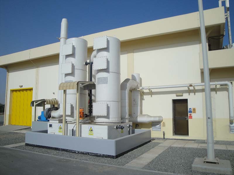
As air laden with chlorine is drawn into the system by a corrosion-resistant fan, the caustic solution makes intimate contact with the gas. This results in the absorption and neutralization of chlorine, promoting safety and preventing harm. The innovative packing media ensures optimal gas removal efficiency with minimal pressure drop.
Compliant with stringent regulations set by government and environmental agencies, the ECSS guarantees trouble-free operation and dependable performance. AmerAir Intl has crafted a solution that not only prioritizes safety but also delivers an economically viable answer to the pressing issue of chlorine emissions.
Working steps of chlorine gas neutralizing scrubbers
The working steps of chlorine gas neutralizing scrubbers are performed in the following order.

As shown in the figure above, the components of the chlorine neutralizing scrubber are as follows :
- The contaminated air transfer system or duct that is responsible for transferring chlorine-contaminated air from the chlorination room or chlorine capsule storage area to the location of the neutralizing scrubber. (Shown in orange in the figure)
- The scrubber body, which is made of GRP and includes a soda storage tank (Sump), two washing towers (Tower). It should be noted that the soda concentration inside the tank is about 20%. Also, because soda is corrosive, the body material must be resistant to corrosion. The chemical process of converting soda and chlorine is an exothermic process that can generate heat up to 60 degrees Celsius. If this process occurs on a hot summer day, the body of the device must be able to withstand at least 100 degrees Celsius. (Shown in light green in the figure)
- Chlorine Detector, which includes a chemical sensor sensitive to chlorine. This sensor needs to be replaced in case of ghosts. The number and location of detectors depends on the volume and shape of the protected area. (Shown in yellow in the figure)
- Vertical anti-corrosion pump whose body and impeller are made of special corrosion-resistant plastic. The pump power and its length vary depending on the tank volume and the scrubber neutralization capacity. (Shown in blue in the figure)
- Anti-corrosion suction fan that is responsible for creating suction to evacuate chlorine-contaminated air from the protected area. The fan power varies based on the building volume and the scrubber neutralization capacity. (Shown in pink in the figure)
- Spray nozzle or spray nozzle that is responsible for spraying the soda onto the packings.
- Packings that are responsible for creating a suitable location by creating the best conditions for chlorine-contaminated air to contact the soda. The type of packing should be such that it creates the least pressure drop with the best surface contact of chlorine and soda. (Shown in gray in the figure)
- First stage

As shown in the figure above, initially a total leak occurs in the protected area. Chlorine leakage will continue until the environmental contamination reaches the ceiling defined in the PLC of the device. Usually, the defined contamination value is 10 ppm, which can be changed at the request of the employer and according to the working and environmental conditions.
- Second stage
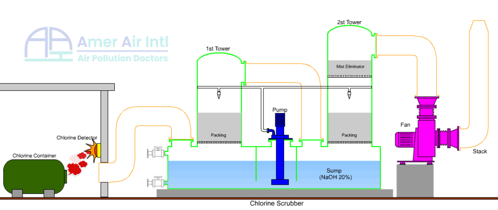
After the pollution limit reaches the value defined in the PLC of the device, the detector sensor activates the detector and the detector starts to sound a weak alarm. This alarm is to indicate the activated detectors, which ultimately helps the operator to determine the location of the leak. At the end of the scrubber neutralization operation, the operator must manually press the detector reset button to stop the alarm sound.
After the detector is activated, the pollution detection command is given to the PLC and the device is ready to start working.
- Third stage

After the contamination detection command is sent to the PLC, the pump first starts working and sprays the brine in the scrubber tank onto the packings through the showers installed inside the towers. It is worth noting that the spray nozzles are of a special type that, by adjusting the brine pressure and the appropriate distance between the nozzle and the packing surface, creates a thin and uniform conical wall so that the circle created at the point where the brine and the packing meet is the appropriate and required size.
- Step Four

After the pump and fan start working, they start working with a 20-second delay. The delay can be changed according to the calculations via PLC and depends on the packing volume and the distance of the scrubber from the protected area. The reason for the delay in starting the fan is due to the need for adequate time for the packings to be wetted with the brine and to create a suitable place for the brine and chlorine to contact for the chemical reaction to occur. If the pump and fan start working simultaneously, the suction speed of the fan itself may cause chlorine to be released into the space outside the chlorination and the surrounding environment.
- Step Five

After the machine is finished and the pollution level reaches below 5ppm (this number can be changed according to the employer’s wishes and environmental and working conditions), the machine is turned off via PLC. By performing the chemical process of chlorine and sodium, the product created in the machine’s tank is Sodium hypochlorite or the same as Chlorine bleach.
- Step Six

At this stage, we change the device from automatic to manual mode through the selector on the PLC panel and drain the scrubber water through the drain valve at the bottom of the scrubber tank. The resulting product is not discarded and is used as a cleaning and sanitizing solution or to adjust the pH of water in drinking water treatment plants. If the leakage amount is small, by testing the available Caustic soda and ensuring its proper concentration and health, there is no need to replace the Caustic soda.
- Seventh and final stage
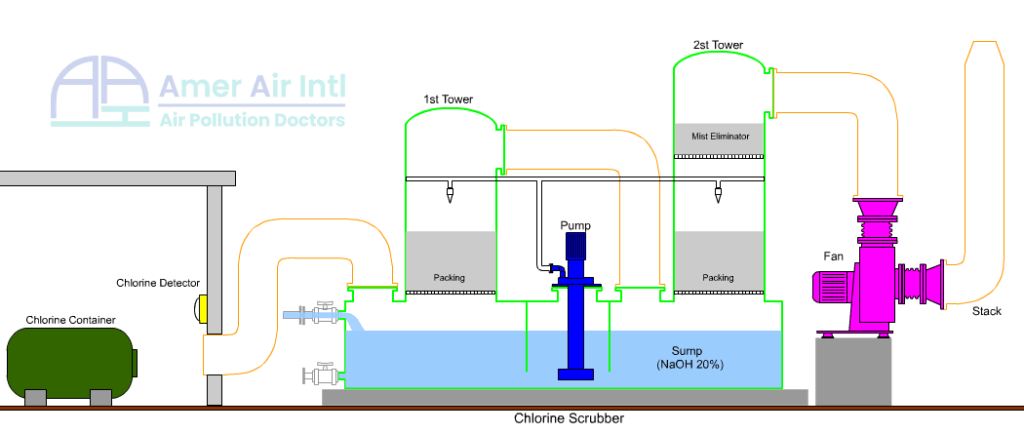
At this stage, we recharge the scrubber tank through the recharge valve located at the top of the scrubber tank. Then, we ensure the health of the sensors through the PLC display. The detectors are shown in their places and with a special code on the display. The green color of the detector indicates the health of the sensor. The yellow color means that the detector is active, and the gray color indicates that the sensor is damaged and needs to be replaced. Then, we change the device from manual mode to automatic mode through the selector on the PLC panel.